Power on your timeline
Behind-the-meter power could support capacity before grid reinforcement arrives, subject to fuel, emissions, permits and site approvals.
CROSSOVER · behind-the-meter generation
Hyper Tech is developing CFM56-derived generation with a front-mounted generator and protected DC delivery.
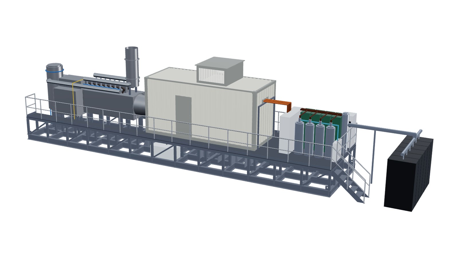 Concept CAD layout as drawn, not a built unit
The bottleneck is no longer just compute. It is the ability to deliver reliable, scalable electrical power to data-centre sites. Hyper Tech's concept pairs turbine generation with a more direct DC delivery architecture.
Behind-the-meter power could support capacity before grid reinforcement arrives, subject to fuel, emissions, permits and site approvals.
A multi-bus machine with on-machine rectification is intended to shorten the path between generation and 800 V DC loads.
Repeatable generator packages offer a potential route to phased campus deployment, with redundancy and energy storage designed into each site.
Rather than treating generation and rack-side power conversion as independent systems, the proposed architecture integrates the electrical machine and rectification around data-centre DC requirements.
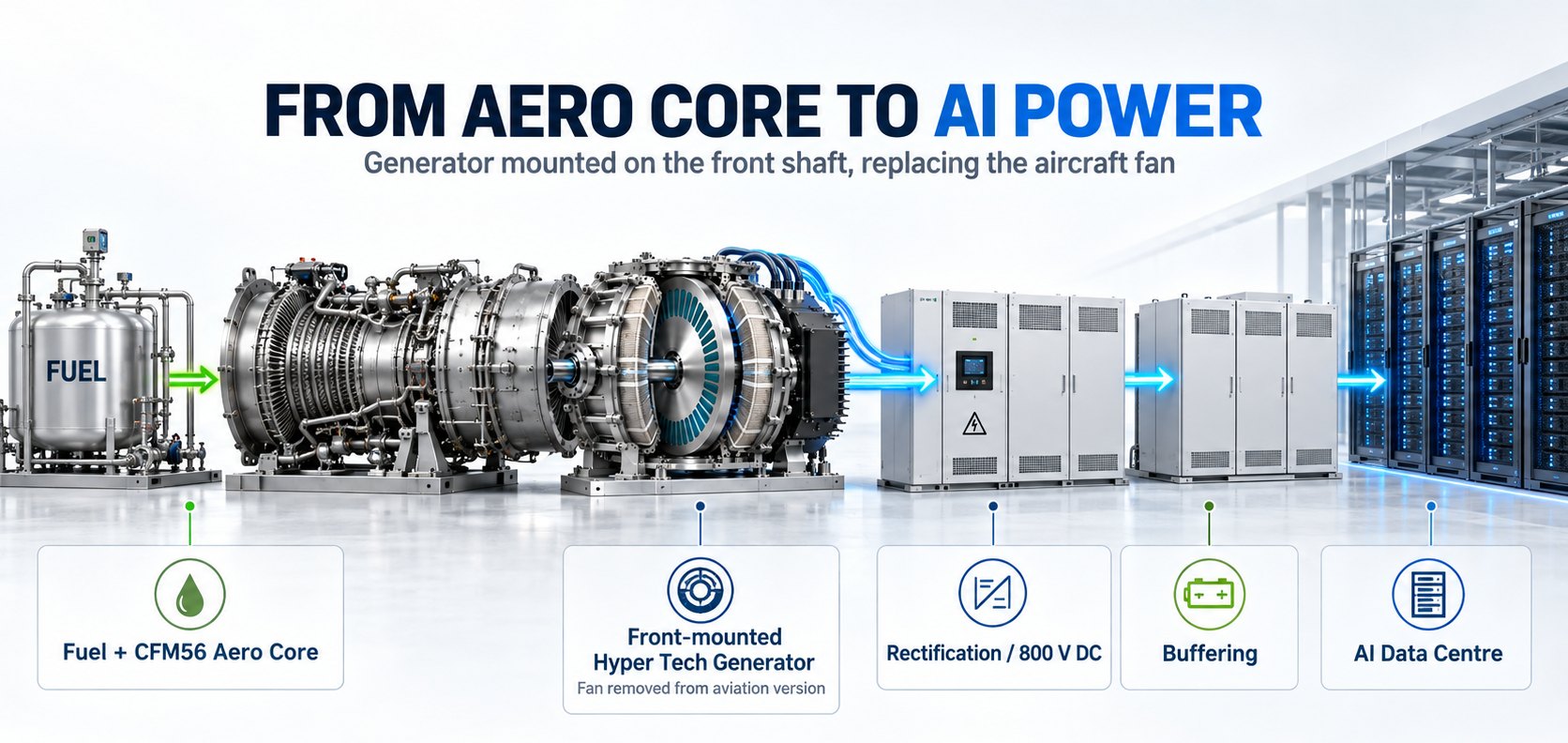
Each installation still requires an engineered electrical protection scheme, safe isolation, UPS/storage strategy, grid-interface decisions where applicable, gas supply, turbine exhaust/emissions compliance, cooling and site approval. The concept does not eliminate these functions.
ConceptTypical infrastructure uses AC distribution and multiple interface stages, with details varying by site and rack design.
Aims to integrate rectification earlier in the conversion chain, while retaining required protection, backup and safety systems.
Each figure on this site traces to Hyper Tech's real-gas cycle model of the CFM56 core, now calibrated against an engine test-cell report, and to a simulation of the skid as designed: generator, DC buses, exhaust loop, rotor stress and shaft transients.
Basis: Hyper Tech cycle model Rev 14 (11 Oct 2026), CFM56-5B3/P donor, continuous rating 100 K below take-off, ISO 15 °C, pipeline gas; boundary = DC output at the generator terminals, before distribution to the racks. Declared component efficiencies; estimates, not guarantees. Detailed results, the 3D skid and the cost of ownership are in the investor area (sign-in required).
Evaluate a data-centre site from the electrical load backwards: available gas supply, required resilience, generation modules, energy storage and distribution to the racks.
Set a unit count, a site temperature and a configuration. Output per unit comes from the cycle model; this is a planning estimate, not an engineered capacity.
Net DC at the generator terminals from the Rev 14 cycle model, × 0.955 DC distribution efficiency to the racks, less one unit if N+1 is ticked. Excludes cooling and IT power factor (PUE), site losses, storage sizing and planned maintenance. No performance guarantee is implied.
The initial commercial development focus is CFM56-derived gas-turbine generation. A fuel-cell pathway is being explored separately with Global Research & Development Inc.
Adaptation of retired jet cores, integrated electrical-machine design and a multi-bus DC output intended for behind-the-meter AI infrastructure. Detailed net efficiency, availability and operating cost require demonstration and validation.
Global Research & Development Inc. is exploring nano-membrane solid-oxide fuel cells with direct-DC output. Stated 60% electrical efficiency and 30–50% lower capital cost are research targets, not validated product specifications.
Prime-mover selection, generator architecture, electrical and balance-of-plant requirements.
Proposed first integrated data-centre generator demonstration by year-end.
First planned site trial to establish performance, availability and economics.
Hyper Tech Research was founded in Columbus, Ohio, in 2001. Its existing capability in advanced conductors, coils, high-power-density motors and manufacturing underpins the proposed move into integrated power generation.
This is an extension of the company's engineering portfolio, not a claim that the data-centre generator is already a commercial product. Existing product lines include MgB₂ and Nb₃Sn conductors, coils, and high-power-density machines.
Leadership: Michael Tomsic, President; Aaron Cairns, Chief Technology Officer.
For data-centre operators, gas-turbine and MRO partners, integrators, investors and research collaborators interested in early deployment and evaluation.
539 Industrial Mile Rd.
Columbus, Ohio
Telephone
+1 614-481-8050Company social profile
x.com/hypertechOH ↗